Evaluation of Pulse Eddy Current Sensor Using KUKA Robotic Arms
Date
July 2022 - June 2023
Location
SEARCH Lab, University of Strathclyde, Glasgow
Project type
PhD Project, collaboration with Inspectahire Ltd. and MAXWELL NDT Ltd.
Role
-
Experimental System Designer
-
Robotic Arm Operator
-
Python Developer for Data Processing & Analysis
Publication
This project explores using UAVs equipped with Pulsed Eddy Current (PEC) sensors for non-contact wall thickness inspection in hazardous or inaccessible environments. Unlike traditional ultrasound, PEC enables remote measurement without surface contact. However, sensor misalignment and aerodynamic factors can affect accuracy.
We evaluated a commercial PEC sensor mounted on a robotic arm to simulate UAV flight angles. A 4° misalignment on a 20 mm steel sample resulted in a measurement error of 0.408 mm. These findings highlight critical design considerations for reliable, autonomous PEC inspections using aerial platforms.


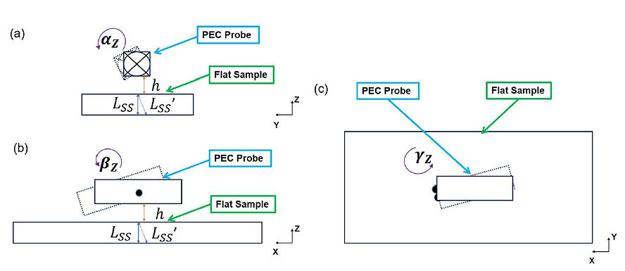
It’s understood that misalignment of the probe can significantly impact the signal, especially if the probe’s front face is not aligned parallel to the target surface. To explore this in the context of UAV manipulations, an experiment was set up using a PEC probe mounted on a KUKA KR6 R900 sixx, an industrial robotic manipulator arm. This setup, as shown in the above figure, allows for precise positioning of the sensor, offering repeatability and accurate measurement essential for assessing alignment constraints.
The PEC operates based on electromagnetic fields, allowing it to function effectively without physical contact. It was positioned at a consistent, small lift-off distance from the sample surface to minimize lift-off effects and avoid collisions when the probe was tilted by the robot.
In contrast to the probe vibrations experienced when mounted on a UAV, the KUKA robot can position the sensor with higher precision at an impressive resolution of 0.01° for angular adjustments and 0.01 mm for translational movements. These adjustments are manually made to navigate the PEC probe without interference from UAV motors.
The probe’s body reference frame as shown in the figure above. The alignment of the probe was controlled to be normal to the Y-axis of the positioner across all tested ranges. Similarly, the lift-off distance was precisely maintained at 5 mm as measured by the robot’s z-axis feedback. The

The test samples were BRT 080A15 carbon steel plates (300 × 200 mm) in three thicknesses: 6, 10, and 20 mm. These thicknesses were chosen to accurately represent the variety of pipes typically used in industries. The use of uniform and flat plates was adopted to establish a controlled baseline for assessing sensor performance. Uniform structures are essential for performance validation because they offer consistent properties that enable precise evaluations of sensor accuracy and repeatability. This ensures that any deviations observed are due to the sensor itself rather than inconsistencies in the structure. Flat plates were selected to simplify the test environment, minimizing the impact of external factors like curvature, surface roughness, and thus providing a clear benchmark for the sensor’s capabilities. Additionally, no coatings or variations in thickness were applied to guarantee that the sensor’s measurements were solely influenced by the alignments, avoiding any masking of the sensor’s true performance and sensitivity by different material properties or layering effects.
For every individual value in the measurement process, the error in thickness was determined as the shortest vertical distance from the top surface point to the bottom one of the samples. However, it must be noted that when the probe is tilted with the angle , then , the measured thickness values change correspondingly.

The RMSE error when the probe was measuring steel samples of different thicknesses. (a), (d), and (g) show results for the 6 mm thickness, (b), (e), and (h) for the 10 mm thickness, and (c), (f), and (i) for the 20 mm thickness. The orientation of the probe was varied, with the roll angle fixed in (a), (b), and (c), the pitch angle fixed in (d), (e), and (f), and the yaw angle fixed in (g), (h), and (i).
Overall, the probe performs bestwiththinnersteel samples, demon strating high accuracy and stability across different orientations. As the thickness increases, the measurement accuracy decreases, with significant challenges observed for 20 mm samples. However, the errors increased by less than 0.5 mm, and therefore the sensor was still working well even with the imperfect alignments. The orientation of the probe plays a crucial role in the measurement accuracy, with f ixed roll and yaw orientations generally providing better stability compared to fixed pitch. These findings highlight the importance of considering both sample thickness and probe orientation to achieve reliable and accurate measurements in practical inspections.